Link to Standard Products Link to Custom Products Link to Case Studies Link to Ceramic and Glass Materials Link to Design Notes Link to Working Together Link to Accuratus Contact Form
link to Accuratus home page email link - voice: 908-213-7070 fax: 908-213-7069

Standard
Products


Accuflect®

MACOR®®

> Fabrication
Machining
Cleaning
Bake Out
Annealing
Thick Film
Metallizing
Thin Film
Metallizing
Frit Sealing
Brazing
Adhesive Bonding

> Properties

> Available Sizes

Ceramic Rod & Tube

Aluminum Nitride Substrates


Machining MACOR® Machinable Glass Ceramic

MACOR® machinable glass-ceramic possesses a unique microstructure, composed of small, interlocked plate-like mica crystals dispersed within the parent glass matrix. These randomly oriented crystals are key to the machinability of MACOR®. The MACOR® machining process is unlike that found in metals and plastics where plastic deformation occurs just prior to chip formation. Material removal in MACOR® is via a controlled fracture process. Like natural mica, it is difficult to propagate a crack through the crystal sheets in MACOR® although the individual sheets can be separated easily along their cleavage planes. Fractures in MACOR® typically follow the glass-mica interfaces and cleavage planes of the crystals. The microscopic fractures are repeatedly deflected, stopped, or branched, effectively arresting the fractures. Since the fractures are localized, and MACOR® is unique in it’s strength insensitivity to surface flaws, MACOR® does not give up strength or hardness for it’s machinability.

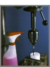
Drilling MACOR® MGC

Drilling Macor image

Drill Size
Speeds and Feeds
Twist Drills
Diamond Core Drills
Spindle Speed
Feed Rate
Spindle Speed
Feed Rate*
6.5mm (1/4") 300 rpm 36mm/min (1.4"/min) 3500 rpm 14mm/min (.5"/min)
12.7mm (1/2") 250 rpm 45mm/min (1.7"/min) 3000 rpm 14mm/min (.5"/min)
19 mm (3/4") 200 rpm 50mm/min (2.0"/min) 2500 rpm 10mm/min (.4"/min)
25.4mm (1") 100 rpm 30mm/min (1.2"/min) 2000 rpm 8.5mm/min (.3"/min)
50.8mm (2") 50 rpm 19mm/min (.75"/min) 1200 rpm 6.5mm/min (.25"/min)
* Feed rates based on 1.4 Mpa (200 psi) coolant pressure through the center of the drill

General Drilling Notes:
1. Leave at least 1.3mm (.050") of material on drill exit side of material for chips.
2. Back up the workpiece where holes must be drilled through. The workpiece can be waxed to the backup to further improve support and minimize chipping.
3. Start and finish the drilling at reduced feed rates—1/2 or less the normal feed rate.
Twist Drilling Notes:
1. Machine wet with flood coolant or machine dry.
2. Drills smaller than 1.5mm (.062") should be machined dry.
3. Holes as small as .1mm (.004") can be machined.
4. Carbide C2 drills are recommended for extended tool life.
5. Maintain sharp cutting edges to minimize chipping.
6. A thinned web drill will reduce cutting forces and allow increased feedrates.
7. Deep holes should be peck drilled with full drill retraction to help remove cutting swarf.
Diamond Core Drilling Notes:
1. Use pressurized coolant supplied through the center of the drill 340 kPa (50psi) minimum.
2. Long holes should be started with a short pilot hole.
3. Drill runout should be less than .15mm (.005").

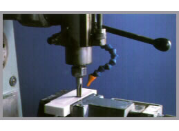
Milling MACOR® MGC

Milling Macor image
Speeds and Feeds:
1. Cutting Speed 1 to 1.4 m/min (20 to 35 sfpm)
2. Feedrate .05mm/tooth (.002"/tooth)
3. Depth of cut 3 to 5 mm (.125"to .200")
Tool Suggestions:
1. Carbide C2 or equivalent recommended for improved life.
2. Two or four flute cutters work well.
3. Do not use chipbreaker or roughing mills.
4. Standard helix milling cutters work well.
Milling Notes:
1. Coolant is suggested for swarf removal and improved tool life. Flood application.
2. Up cutting or climb milling is recommended when milling an edge to minimize chipping.
3. When milling an edge depth of cut should not exceed one half of cutter diameter.

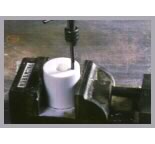
Tapping MACOR® MGC

Tapping Macor image
Tapping Notes:
1. Make pilot hole one drill size larger than typically used for metals.
2. Use a lubricant while tapping. Lubricant can be hand applied. Tapping fluid or detergents both work well.
3. Tap to bottom of hole before reversing the tap.
4. Chamfer the entrance and exit of the hole prior to tapping to minimize chipping.
5. Four flute taps are suggested.
6. Pipe threads are difficult to form. If they are necessary, a tapered pilot hole must be used.
7. Use the center at the back of the tap handle to assure the tap axis is parallel to the drilled hole axis.

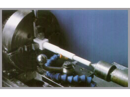
Turning MACOR® MGC

Turning Macor image
Speeds and Feeds
1. Cutting Speed 9 to 45m/min (30 to 150 sfpm) using carbide tools.
Speed is limited to 15m/min (50 sfpm) when using high speed steel cutters
2. Feedrate .05 to .13 mm/rev (.002"to .005"per rev)
3. Depth of cut up to 6.3 mm (.250")
4. When threading depth of cut should not exceed .04mm (.0015")
Tool Suggestions
1. Carbide C2 or equal suggested for best life
2. Tool should have zero to 5° positive rake angle
3. Use an “up sharp” tool. No honed edge
4. A nose radius of .38mm (.015") or larger will help minimize chipping
5. Using a tool with side cutting angles from 15° to 45° allows for increased feedrates

Sawing MACOR® MGC

1. Macor can be sawn with a bandsaw. Carbide grit edge blades work well with a blade speed of 30 m/min (100 sfpm).
2. Toothed blades of high speed steel can be used but blade life is short. Teeth should be small without chip breakers.
3. Thin diamond wheels are effective. Coolant must be used. Wheel speed of 1800 m/min (6000 sfpm), depth of cut up to .25mm (.010") table traverse rate 6 m/min (20 fpm).

Grinding MACOR® MGC

1. Aluminum oxide, silicon carbide or diamond wheels can be used. They must be constantly monitored to ensure the wheel is sharp. A dull wheel will cause surface cracks. Diamond is vastly superior.
2. Aluminum oxide and silicon carbide wheel grades 36 or finer with open grain.
3. Diamond wheels 100 to 220 grit (US mesh size) work exceptionally well.
4. Coolant must be used.
5. Downfeeds with aluminum oxide and silicon carbide should not exceed 13 microns (.0005").
6. Downfeeds with diamond can be up to .5mm (.020")
7. Table traverse rate up to 3 m/min (10 fpm)
8. Crossfeeds up to one half the wheel width.
9. Grinding can be done in both directions. A sparkout pass is not necessary.

Polishing MACOR® MGC

1. Polishing can be performed wet or dry.
2. Rough plano polishing: steel disk rotating 60 m/min (205 sfpm), A-700 paper with 300 g/cm2 (4.5 psi) down force. Best done wet.
3. Mirror plano polishing: steel disk rotating 140 m/min (465 sfpm), A-2000 paper with 300 g/cm2 (4.5 psi down force. Best done dry.
4. Curved surfaces can be polished with cerium oxide powders using standard optical polishing techniques

General Considerations When Machining MACOR® MGC

1. Thoroughly deburr all workholding devices.
2. Protect the MACOR® from direct contact with the hard surfaces of the workholders. Tape is a good choice. Where critical tolerances are required this cannot be done.
3. Avoid clamping on the edge of the MACOR®. If it cannot be avoided, round the edge of the MACOR® at least .25mm (.010")
4. Avoid cutting in a direction that puts the MACOR® under tensile stress at an edge.
5. Waxes are a good work holding material. Avoid heating and cooling the MACOR® at a rate greater than 200°C/hr. Temperature differences on the MACOR® part during heating should not exceed 48°C (118°F).
6. Where features go through the MACOR®, machining can be performed from both faces to minimize chipping.
7. MACOR® is a brittle material that should be inspected for flaws prior to use. Machining damage will usually be open and closed chips at an edge, small surface cracks on machined surfaces usually due to dull tools or cracks from excessive workholding or cutting forces. Flaws in parts up to 3mm (.125") thick can be inspected by shining a bright light through the material. The flaws will appear as shadows or bright lines. Alternately, any of the industry standard colored dye penetrants may be used. Follow all manufacturers recommendations and safety instructions.
 

See also: Materials > MACOR®

Standard Products | Custom Products and Services | Case Studies | Materials
Design Notes | Working Together | Vision | Contact Us | Site Map

1-908-213-7070

© 2013 Accuratus

Site Design M. Adams