Accuflect®
Reflector Design
Notes
Accuflect®
Design
for Manufacturability
Accuflect® B6
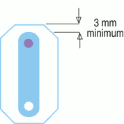
1. Maintain at least a 3mm wall thickness where possible to minimize
breakage in manufacture and use. It will also provide full
reflectance.
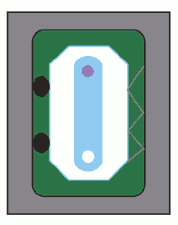
2. Do not design seal surfaces into the reflector. Rely on the metallic
pump chamber or flow tubes with elastomer seals to provide necessary
sealing surfaces.
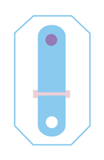
3. UV filter glass can be incorporated to improve laser rod lifetime.
The flat glass sheet can be mounted in slots on the inner reflector
surface. Slots should be at least 1 mm deep to adequately trap the
filter glass.
4. Do not use threaded mounting holes in the reflector.
5. Limit reflector size to 75 mm diameter or square by 250 mm long if
possible. Multi-part designs for larger geometries can be accomodated.
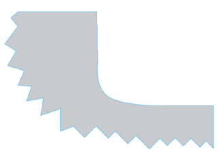
6. Design for a maximum fillet radius of .5 mm
7. Tolerances as tight as 25 microns can
be produced. Try to keep
tolerances at +-.1mm to minimize extra costs.
Accuflect®
G6
1. The same notes listed for Accuflect® B6 apply except with a few
exceptions.
2. Design for open tolerances. A general rule is +-0.3mm.
3. Passive mounting using compliant components is suggested. Components
such as o-rings and springs work well.

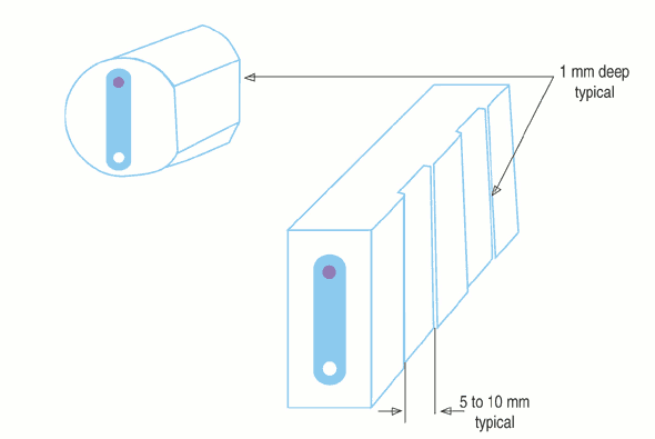
4. Provide a support surface for
holding the
ceramic during glazing.
Relieved areas 1mm deepwork well. Flat bottom grooves extending across
or along the part work best.
5. Design for a maximum fillet radius of 1 mm.
6. Assume mounting surfaces are not flat. Flatness may vary as much as
.15 mm so strive for three point registration.
7. Radius all external sharp edges at least .7 mm.
Accuflect®
Optical
Design
1. Maintain at least a three mm thick wall to minimize light leakage
through the Accuflect® material.
2. If a split design is being considered, use lap joints to minimize
light leakage.
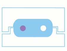
3. Keep the inside shape of the reflector simple. Oval shapes are good.
There is no need for complex or critically toleranced paraboloid or
ellipsoid focusing geometries since the reflected light is scattered by
the reflector.
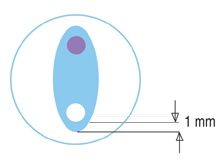
4. These are designed to be close coupled reflectors. Keep reflector
walls as close to lamps and laser rods as possible consistent with
adequate cooling. One mm clearance is a good starting point for design.
5. Avoid split designs with Accuflect® G6. The glaze is clear and may
result in excess light leakage through the joint.
Low
Cost Accuflect® Design
1. Keep external shapes simple. Cylinders or rectangles are best.
2. Avoid drilled mounting holes. Look for mounting techniques other
than screws.
3. Avoid selective surface glazing with Accuflect® G6.
|


